
ELECTRONIC DESIGN
SIGNAL PROCESSING
Requirement: It is required that 6 stepper motors are to be independently controlled through the Line Printer Port of a Standard PC.
Logic Used: The LPT port has 8 separate data lines, which can be controlled independently. Our circuit logic uses these lines in the following manner. The first line Most Significant Bit is used to enable the circuitry. The next 3 lines are used to address the motors, hence we can address a maximum of 8 motors which is more than required by us. The next 4 lines are used to generate the step sequence used to energize the 4 coils of the stepper motors through adequate buffering and hence drive the motors.
Working of the circuit: The data from the LPT is delivered spatially (in parallel) to all the 8 data lines. By setting the MSB to high we enable this circuitry by enabling the 3:8 decoder (74LS138).
The next 3 lines are used as the address bus to select the motor. Depending on the value of the address bus, one of the 8 lines of the 3:8 decoder goes low as according to the truth table shown below. (for more details on the IC refer the appendix).
Truth Table of Address bus
|
Selection of Motor |
Address Bus |
Bit 2 |
Bit 3 |
Bit 4 |
|
Motor 1 |
0 |
0 |
0 |
|
|
Motor 2 |
0 |
0 |
1 |
|
|
Motor 3 |
0 |
1 |
0 |
|
|
Motor 4 |
0 |
1 |
1 |
|
|
Motor 5 |
1 |
0 |
0 |
|
|
Motor 6 |
1 |
0 |
1 |
|
|
Motor 7 |
1 |
1 |
0 |
|
|
Motor 8 |
1 |
1 |
1 |
Since the output of a 3:8 decoder is active low, we invert the signal using a Hex Inverter (74LS02). The selected line that now goes high is fed to the enable of an 8 bit latch (74LS373). This Latch, when enabled, causes the data from the data lines to pass through transparently. When a certain latch is enabled, all the remaining latches are disabled and this causes the motors to be locked in their previous positions as it latches the data when disabled.
The next 4 lines are used as the data bus. The step sequence used to run the motor is supplied here as shown in the table below.
|
Step Sequence to run a stepper motor |
|||||
|
Bit 5 |
Bit 6 |
Bit 7 |
Bit 8 |
||
|
Step 1 |
1 |
0 |
0 |
1 |
|
|
Step 2 |
1 |
0 |
1 |
0 |
|
|
Step 3 |
0 |
1 |
1 |
0 |
|
|
Step 4 |
0 |
1 |
0 |
1 |
|
|
Step1 |
1 |
0 |
0 |
1 |
|
Thus by supplying 8 bits, (a byte) to the LPT port (&H378 or &H3BC in most computers), we can effectively select a motor and then supply the required step to turn the motor.
Example: a byte such as 10011001
The MSB being high (1) would enable the circuitry
The Address bus contains 001 which would enable the latch of the Motor 2 thus allowing the data to flow through transparently.
The Data Bus contains 1001 which is the bit equivalent to the first step.
The above example thus causes motor 2 to be locked at the first step position.
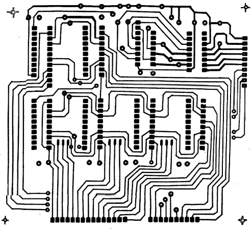
Circuit Design: The circuit was designed and drawn manually by us. The logic of the circuit was found to be accurate with tests conducted on breadboard and general purpose PCB. After verifying the accuracy of our designs in this manner we got the circuit professionally built using custom PCB artwork as shown below.
Fabrication of the circuitry: The PCB artwork thus provided by us was converted to a double sided PCB on a green masked printed circuit board. The assembly of the components and testing was done professionals and the board was tested extensively by us.
Advantages and disadvantages:
The primary disadvantage in this logic is that only one motor can be controlled at a given instant. But due the fast switching times of the TTL transistors and the amplifiers we can effectively multiplex the data so as to make the motor appear to move synchronously. This is done by the driving software and more of this is discussed in module 3.
Alternative Logic:
Involves use of Step sequence generators like (IC555 timer) which frees up the processor for calculations and use of the 6 data lines to choose the motor, 1 to specify direction. which gives us the obvious advantage of running more than one motor at a time. We did not choose this because the complexity in electronic circuitry defeats the purpose of this being a mechanical project.
SIGNAL AMPLIFICATION
Requirement: The decoded signal from Module1 and the data from the PC is very weak and does not have enough power to drive any stepper. It is for this reason that we see the necessity of signal amplifiers to drive the stepper motors.
Logic Used: The torque’s that we require range from 0.3 to 10 kg-cm (as will be discussed in the mechanical design). For such motors the current rating varies from 0.5 watts to 1.5 watts per phase. Thus the maximum current drawn by the robot will be 4.5 amps from the 10kg-cm stepper motor.
The transistors chosen to perform this amplification will vary from motor to motor depending on the individual power requirements. To avoid this we decided to base the design of our amplifiers on the motor that requires the highest torque namely the 10kg-cm motor.
The problem that we encounter in signal amplification of such relatively high currents was that single transistor solutions were not available in the market easily and the solutions that we could design were invariably imported and VERY costly. It was for this reason that we had to design and build our own darlington pair transistor amplifier circuits.
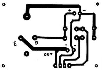
Working of the Circuit: The low amperage current the comes from the latch has to be amplified in order to meet the individual motor specifications. This is achieved by the following circuitry as shown in the figure.
The circuit consists of a Darlington Pair which is nothing but a combinations of two transistors. The two transistors that make up the Darlington Pair in this case are BC147 and 2N3055. When the pilot signal at the base of the first transistor is high, there is a sufficient drive at he base of the second transistor and hence the circuit is complete. Thus a signal amplification occurs at each of the transistors and an overall two stage amplification provides the necessary amperage to meet the individual motor specification. As two transistors are used for every coil of the motor, a total of eight transistors, four of each kind are required for a single motor. Thus a total of forty-eight transistors, twenty-four of each kind (BC147 and 2N3055) are used in the circuitry.
As the coil of the motor is treated as an inductive load, the charging and discharging of the coil is very fast. In order to cater to this need of the coil, a capacitor (25V 1000m F) has been included in the circuit. The main function of this capacitor is to provide the charge required by the coil of the motor instantly.
A diode (1N5408), is also provided in the circuit to prevent any back e.m.f. to the coil of the motor that may be produced by the momentum of the moving parts connected to the motor
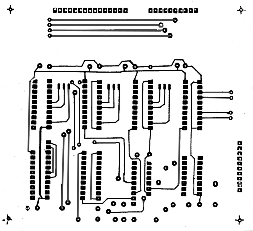
Fabrication of the Circuit:
The PCB artwork was obtained as below on transparency and that was converted to a green masked printed circuit board.
PCB artwork:
Advantages and Disadvantages:
The primary advantage of using Darlington Pair amplifiers is the simplicity of the circuit but this is offset by its undesired large size.
Alternative Solutions:
There were 3 traditionally used approaches to this problem in signal amplification depending on the type of electronic device that we decide to use. They involved the use of:
The MOSFET design was not preferred since it involved working with technology that all of us were not very comfortable with. The knowledge required to design MOSFET circuits required us to first familiarize ourselves with it and then attempt to design circuits. This we felt defeated the purpose of this being a mechanical project.
Step generators are commercially available in the market but incorporating one such crystal/IC driven circuit would involve major changes in the interfacing design. The other obvious disadvantage of using one such generator was the fact that the step speed will remain constant hence the motor speed will essentially remain constant and hence acceleration will not be possible. It was these factors that made us decide against it.
We thus decided to use Darlington Pair transistors to achieve amplification. We were aware that Darlington pairs made by MOTOROLA and other companies are commercially available in the market but these are very costly. We hence decided to construct our own Darlington pair amplifiers by coupling one 100m A transistor (BC147) with a power transistor (2N3055) as shown below.
REGULATION
Requirement: The voltage commercially available in India is 220V A.C. at 50 Hz. The operating voltages of our motors and electronics range from 5V to 12V D.C. Thus it is required to drop the voltage and convert the AC to DC.
Logic Used:
Step down transformers with a 2 Amps Wattage were employed to drop the voltage from 220V AC to 20.7V A.C. Using a bridge rectifier the AC was converted to D.C and by using the appropriate metal regulator the voltage was brought down to a uniform 12, 8.6 or 5V as required.
Working of the Circuit: The specified voltage of each of the motor is achieved by the voltage regulation circuit. 220 V ac is drawn from the mains into the circuit. A fuse whose rating is 3A is provided so as to limit the current to the circuit at 3A. A bipolar switch ensures the proper control of the current into the circuit. An emergency switch has been provided to cut off the signal to the circuitry in case of any eventuality faced during the operation of the system. From the emergency switch, the signal flows into the transformers. Step down transformers, which have been used step down the 220V ac to 15V ac. There are seven transformers, six to cater to the six motors used and one to run the signal processing circuitry.
The next stage of circuitry involves a full wave bridge rectifier circuit which converts 15Vac to 20.6V dc. This dc voltage is the brought to the correct voltage specifications of the motor by the help of metal voltage regulators. The table of the metal regulators used is as follows;
| Motor Used | Voltage Required | Regulator Used |
| Gripper | 12 Volts | 7812 |
| Wrist Roll | 12 Volts | 7812 |
| Wrist Pitch | 12 Volts | 7812 |
| Elbow | 8.6 Volts | LM317 |
| Shoulder Pitch | 5.4 Volts | 7805 |
| Shoulder Swivel | 8.6 Volts | LM317 |
Thus the rated voltage for each of the motor is achieved.
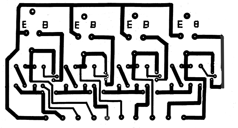
Fabrication of the circuit:
The circuit was fabricated as per the PCB artwork shown below for the three regulation types.
PCB artwork:
 7805 Metal Regulator
PCB
7805 Metal Regulator
PCB
 LM317 variable
regulator circuitry
LM317 variable
regulator circuitry