Computer Interfacing
Introduction:
The hardware will be interfaced to the LPT port (usually address &H378 also called centronics port). An option for using the address &H3BC is also provided. The 8 data lines of the printer port are utilized as discussed in the electronic design.
The software has been built using Visual Basic 4.0 Enterprise Edition. It has been built for operation on the the Windows95, 32 bit GUI platform. The kernel has been written as a standalone EXE in Borland C++. The interface framework is ready, and is available as a testing Beta release. The software will run under the following modes:
We have opted for an Interface/Kernel type of an programming structure. The Front end Interface was provided by Visual Basic and the Backend was developed in BASIC for the file handling subroutines and Turbo C for the port queing and control and signal processing subroutines.
The Software we developed is titled MARIP (Multi-Axes Robotic Interface Program). It is capable of running in 4 modes of control establishing complete control of the robotic hardware.
MARIP AND OPERATIONAL MODES
The software can be executed in four modes namely:
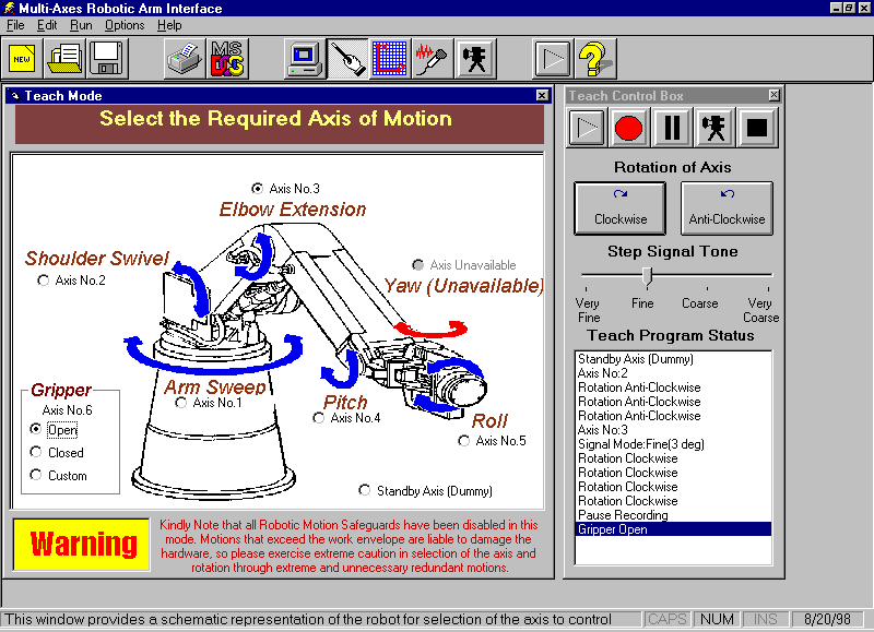
TEACH MODE
Introduction
The teach box is one of the most common aspects of a robot. Every robot should necessarily have a teach box. Generally the teach box is a hardware unit of the robot, which learns new motions.
In ARNOLd, however software teach mode has been introduced which simplifies the process of teaching and replicating the motion.
Usage
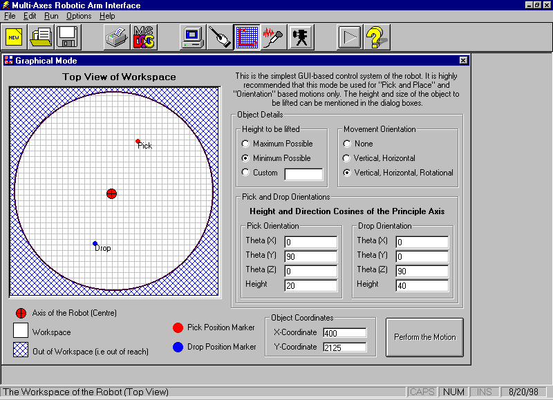
GRAPHICAL MODE
Introduction
The graphical mode is a user-friendly mode of the ARNOLD and helps in the pick and drop operations.
Usage
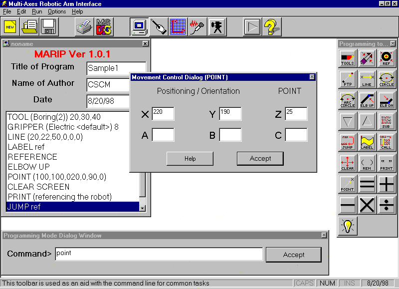
PROGRAMMING MODE
Introduction
This is a mode used extensively by the industry and programmers around the world. For the purpose of offline programming that is essential to all industrial applications, this is the most versatile method of controlling the robot. It involves part programming depending on the application. Generally for all programming applications a standard set of commands are defined and the programmer has to use these commands to manipulate the motion of the robot.
On similar lines our programming package contains a set of predefined commands that can be used to achieve the required task from the robot.
The controlling software MARIP is a completely Graphical based program that provides the user an AutoCAD type command line interpreter and toolbar. Building this mode involved writing our own interpreter, which was capable of understanding the program that could be written with any standard editor.
The usage of this mode can be as easy as specifying the real world coordinates (of the object in the workspace of the robot) with a keyword and when executed, the robot would perform the task. Thus the programming language we have developed (called RIP-Robot Interface Program) would allow even a novice programmer to handle the robot in this mode.
The working of this is accomplished by using the principles of Inverse Kinematics. For further details refer the appendix.
Alphabetic Listing of Keywords
This specifies the type of gripper used and the state of the gripping jaws/surfaces etc. Pneumatic, Hydraulic, Magnetic and Electric grippers can be used but the default is Electric.
Syntax:
GRIPPER (<type of gripper>) <state>
<type of gripper> - specifies the name of the gripper in the tool palatte.
<state> - specifies the state of the gripper
1 – Opens the gripper (100%)
2 – Opens the gripper (50%)
3 – Opens the gripper slowly
4 – Opens the gripper very slowly
5 – Closes the gripper very slowly
6 – Closes the gripper slowly
7 – Closes the gripper (50%)
8 – Closes the gripper (100%)
Example:
GRIPPER (Electric <default>) 4
Note:
The only gripper that is available as a part of our project is the electric one.
This is used to specify the tool and the size of the tool.
Syntax:
TOOL (<tool name>) x,y,z
<tool name> - gives the name of the tool from the palatte
x – specifies the x (length) of the tool
y – specifies the y (breadth) of the tool
z – specifies the z (width) of the tool
Example:
TOOL (Boring) 20,40,40
Note:
The reference x,y,z is given from the midpoint of the gripper pads.
References the robot. i.e. brings the robot to the home position.
Syntax:
REFERENCE
Performs Point-To-Point Motion.
Syntax:
PTP (x,y,z,a,b,c)
X,Y,Z – specifies the x,y,z coordinates of the point with reference to the robot
A,B,C – specifies the tool orientation
Example:
PTP (200,200,300,0,0,90)
PTP (-200,100,300,0,0,-90)
Note:
This statement is used in pairs to specify the start and end point.
Performs linear motion.
Syntax:
LINE (x,y,z,a,b,c)
X,Y,Z – specifies the x,y,z coordinates of the point with reference to the
robot
A,B,C – specifies the tool orientation
Example:
LINE (200,200,300,0,0,90)
LINE (-200,100,300,0,0,-90)
Note:
This statement is used in pairs to specify the start and end point.
Circular trajectory of the tool
Syntax:
CIRCENT (x,y,z,a,b,c)
X,Y,Z – specifies the x,y,z coordinates of the point with reference to the robot
A,B,C – specifies the tool orientation
Example:
CIRCENT (200,200,300,0,0,90)
CIRCENT (-200,100,300,0,0,-90)
Note:
This statement is used in pairs to specify the start and end point.
Resolves the elbow redundancy by choosing the upper configuration.
Syntax:
ELBOW UP
Resolves the elbow redundancy by choosing the lower configuration.
Syntax:
ELBOW DOWN
The object to be picked is available at the front of the robot.
Syntax:
FRONTSIDE
This is the opposite of FRONTSIDE and replicates the Inverse Kinematics configuration in the back of the robot. This is achieved by changing q 1 by 180 degrees.
Syntax:
BACKSIDE
This is an unconditional program control branch.
Syntax:
JUMP <Label Name>
Example:
JUMP ref
Note:
The subroutines must be defined separately at the end using a SUB statement.
This provides a label to the part of the program.
Syntax:
LABEL ref
Clears the output screen.
Syntax:
CLEAR SCREEN
Prints text, variable values in the output screen.
Syntax:
PRINT(<text to be typed>)
Remark Statement
Syntax:
REM <string>
<string> - remark text limited to 72 characters
Example:
REM this is a sample program
This brings the end effector to the desired point in space.
Syntax:
POINT (x,y,z,a,b,c)
X,Y,Z – specifies the x,y,z coordinates of the point with reference to the
robot
A,B,C – specifies the tool orientation
Example:
POINT (200,100,147,0,30,0)
Note:
This statement can be used individually.
Arithmetic Declaration
Syntax:
LET <variable>=<constant>
Example:
LET X=200
Arithmetic operator.
Syntax:
ADD <variable> = <constant> + <variable>
Example:
ADD Z = X+Y
Arithmetic operator.
Syntax:
SUBTRACT <variable> = <constant> - <variable>
Example:
SUBTRACT Z = X - Y
Arithmetic operator.
Syntax:
DIVIDE <variable> = <variable>/<variable>
Example:
DIVIDE X = W/Z
Note:
Even constants can be used instead of the variable
Arithmetic operator.
Syntax:
MULTIPLY <variable> = <variable>*<variable>
Example:
MULTIPLY X = W*Z
Note:
Even constants can be used instead of the variable
VOICE MODE
This mode is a unique feature of our robot and the usage of this including the integration of this mode with the remaining modes is discussed below.
Speech Recognition (SR):
Any SR system has to preprocess the human speech (capture the speech input and convert it into the form the computer can deal with), recognise it (identify what has been said), and communicate it to the hardware and software for action to be taken by the computer. But this is easier said than done. Human speech, like all sound, is analog, it has to be turned into digital form if the computer has to understand it. This is done through digital signal processing techniques, mostly digital audio soundcards, But there is a catch. The quantity of data in the human sound wave is mind boggling - the spectrum of human speech stretches across 20,000 frequencies, right from 20Hz to 20,000Hz . Processing so much data for every nanosecond of speech can overwhelm a PC and you can safely retire and go back to sleep before your computer gives a response to your voice command.
The trick is to drastically reduce this data without losing out on critical information. This is done by using filters to screen out frequencies above 3,100Hz and below 100Hz, as most of the frequencies that enable us to distinguish between two sounds lie within this narrow bandwidth.The speech signals thus obtained are digitised by the respective hardware device in the computer (sound card).
Software aspect of SR :
Once the computer has digitised your speech waveform ,it is ready to identify what you have said. All SR systems do this in one way .By storing already digitised models of words for reference, and comparing the incoming stream of acoustic parameters with these stored models. The best match is recognised as the spoken word.
The collection of these stored models is called the vocabulary of the system. The active vocabulary of an application is the list of words a system can recognise, that is, the computer won't have the foggiest idea about the words that do not figure in it's vocabulary. The active vocabulary of some application is expandable. It comes with an online dictionary which allows you to pull words out of it and inset them in active vocabulary. Even till mid-80's , vocabularies of 1000 words were considered large , but now this limit has gone upto 20,000 words and more, with some applications having vocabulary upto 50,000 words.
There are several ways in which the computer tries to recognise what you have said.
Template Matching:
A template is a set of values for the parameters used by the system to represent speech. In this, each word in an application is stored as a separate template. The spoken input is turned into a template and compared with the templates of various words. The best match is identified as the input word. There must be atleast one template for a word in the vocabulary. This recognition technology was popular till the 80's, has gone out of favour now, though it is still used for speaker verification and apps with small vocabulary.
Phoneme Recognition:
While template matching works at the word level , this technology works at the phoneme - the basic sound segments in a language - level. The number of representations that must be stored in this is limited to the number of phonemes in a language, which in english is around 40. This approach identifies and labels individual phonemes in the input, and the best matching a sequence of phonemes is identified as the input item. This technology is also rarely used today.
Hidden Markov Models:
This is currently the most popular SR technology appearing in a majority of SR apps. It is based upon something called the Hidden Markov Model (HMM). A HMM contains statistics about all spoken samples of a word and uses complex statistical and probabilistic analyses to tie acoustic information together into words and sentences. This is most often used to recognise speech at the word level or for a variant of the phoneme level, called the subword level.
Neural Networks: The next generation of SR technology would consist of something called neural networks. These networks try to create artificial intelligence by modelling the functions of human brain. They are formed by interconnected nodes, which do parallel processing of the input for fast evaluation. Like humans, they learn new patterns of speech automatically, just by coming across them a few times. The RSC series of chips by Sensory Circuits contains a neural network that performs SR.
Once speech input is identified by the above ways, it is communicated to hardware and software for necessary action.
For our purpose we have used a commercially available voice recognition package to control the robot. Any SR package will do as long as it permits shell scripting.